Based Engine Control Panel
Visit the Be124 EC-GSM engine control panel page. You can control & monitor your diesel engine using your mobile phone. It works with standard or CANbus engines (Perkins - Deere - Volvo - Scania - Iveco - CAT- JCB). Purchase the panel or save money by purchasing the KIT of components.

Diesel Generator Control Panel Wiring Diagram Be124
In this wiring diagram you can see the details on how to make a generator control panel using the Be124 generator controller.
Diesel Generator Control Panel Wiring PDF
BE124 Generator Controller Tutorial
Purchase the Be124 Diesel Engine Controller
You can observe the GENERATOR [1] connected to the LOAD via the CURRENT TRANSFORMERS [2] and the GENERATOR CIRCUIT BREAKER [3].The coil of the circuit breaker is driven by the GCB relay [6]. The BE124 can monitor the EARTH FAULT CURRENT via a current transformer [4]. In order to protect the cables we recommend that you use fuses of proper size [5]. You can connect driver relays [7] to the JF removable plug. [8] and [9] allow you to connect ECU and ancillary computer equipment. You can use 12 or24V battery [11]. The Be124 detects speed via a pick-up [12]. Be124 accepts analog & digital signals [13] & [18]. You are required to provide relays for starter and auxiliary equipment if required [17]. The Be124 accepts belt alternator [14] with D+ or / and 'W'.

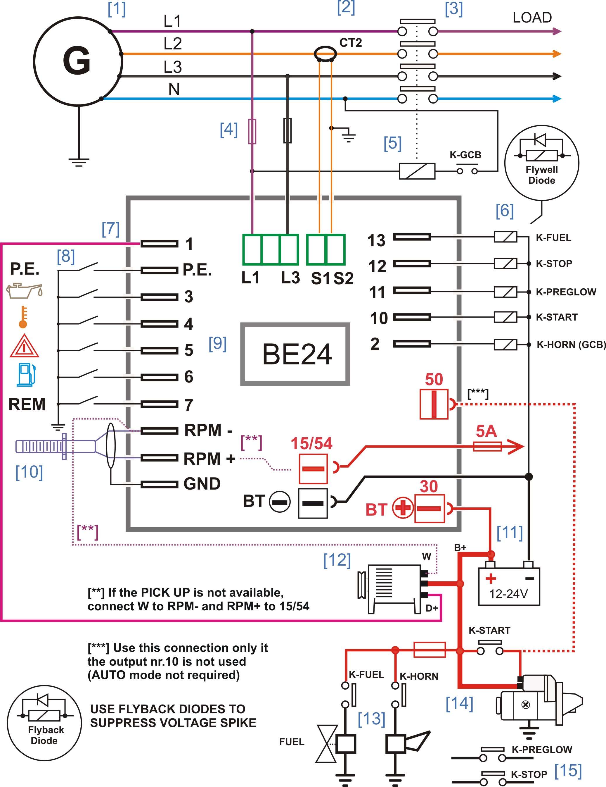
Diesel Generator Control Panel Wiring Diagram Be24
In this wiring diagram you can see the details on how to make a generator control panel using the Be24 generator controller.
Diesel Generator Control Panel Wiring Diagram Be24
Be24 Diesel Generator Auto Start Tutorial
Purchase the Be24 Diesel Generator Auto Start
You can observe the GENERATOR [1] connected to the LOAD via the CURRENT TRANSFORMER [2] and the GENERATOR CIRCUIT BREAKER [3].The coil of the circuit breaker is driven by the GCB relay [4]. In order to protect the cables we recommend that you use fuses of proper size [4]. You can connect driver relays [6] to the output blade terminals.You can use 12 or 24V battery [11]. The Be24 detects speed via a pick-up [10]. Be24 accepts digital signals [8]. You are required to provide relays for starter and auxiliary equipment if required [15]. The Be24 accepts belt alternator [12] with D+ or / and 'W'. Relays mus be provided for FUEL SOLENOID [13], AUDIBLE SIGNAL[13].You can start directly the engine with the key switch or use a pilot relay for automatic use [14].

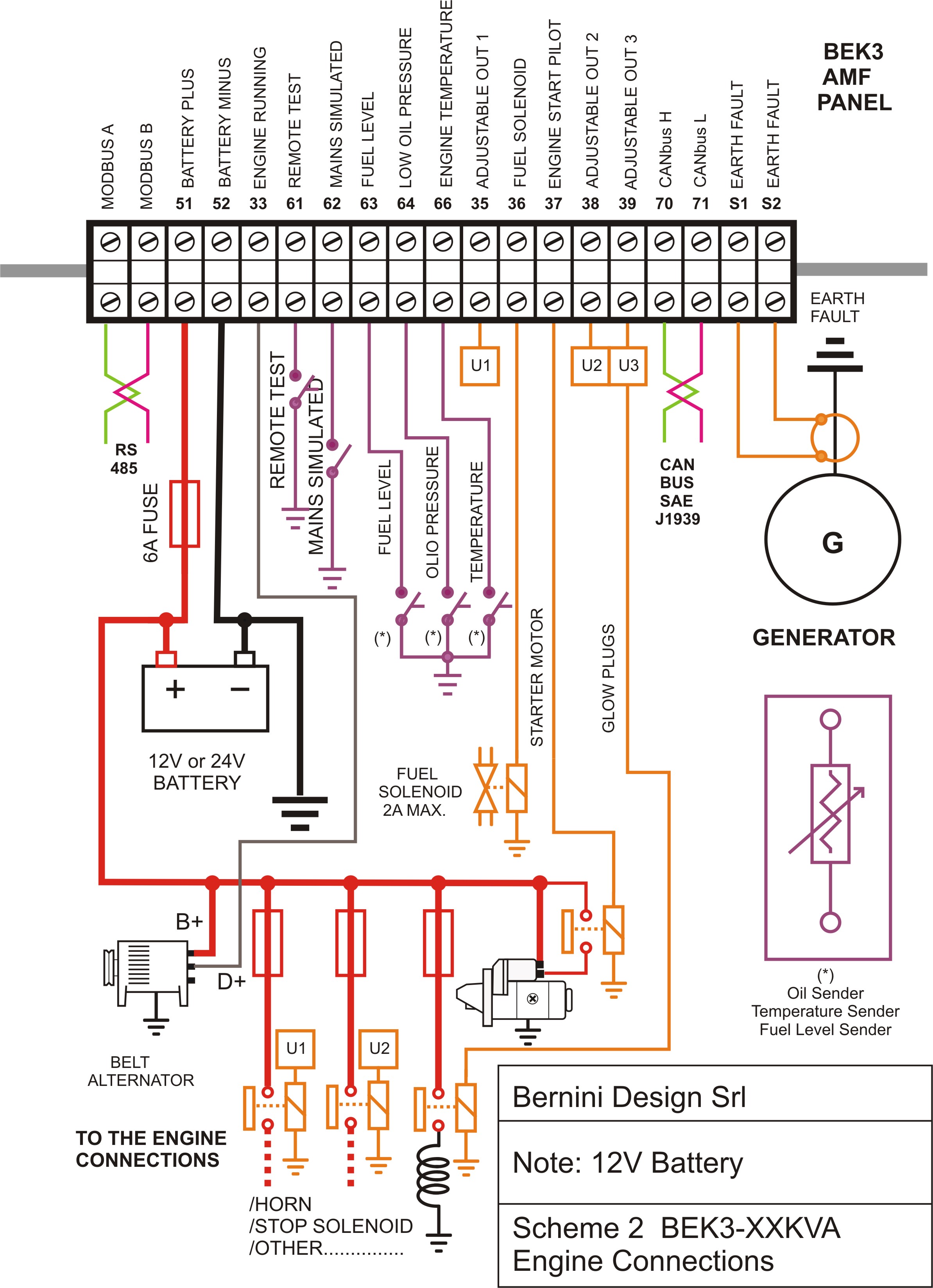
Generator Control Panel Equipped with BeK3 Wiring Diagram
In this wiring diagram you can see the details on how to make a generator control panel using the BeK3 generator controller. This is a general wiring digram, it indicates all features of a state-of-art AMF ATS control panels. You can reduce the number of components according to your needs.
Diesel Generator Control Panel Wiring Diagram BeK3
AMF ATS Genset Controller BeK3 Tutorial
Purchase the BeK3 AMF Controller
Alternative connection of the current transformers
An interesting feature is the possibility to connect the current transformers on the LOAD side. In this way you can get the current measurements when load is connected to the power utility. Please note that the over current alarm (WARNING or SHUTDOWN) are active only when the LOAD is connected to the generator. This avoids alarms when the load is normally connected to MAINS. The display clearly indicates if it is about Generator Current or Power Utility Current.

Engine connections of a generator control panel fitted with BeK3 AMF controller
The Bek3 AMF panel interfaces with automotive relays. This is the best option: in case of failure you can find an automotive plug-in realy in a shop in your street. You are required to use 90-200 OHM dc coil relays (12 V or 24V, according to your engine battery). In case of troubles, you are not required to change the controller! The Bek3 provides over voltage protection and all outputs are short circuit proof. This will add more reliability to your installation. A BEK3 AMF panel can interface with ANALOGUE and DIGITAL sensor fitted on the engine. In other words you can use any kind on diesel engine on the market. Terminals for RS485 serial interface are provided in case you need to control and monitor the panel by remote. Software is provided free of charge. You have a wide choice of accessories for MODBUS, GSM or TCP-IP monitoring. When your diesel generator is driven by an SAE J1939 compatible engine, we recommend that you connect the CANBUS port. In this case sensors are no longer necessary.The BeK3 features 3 fully adjustable outputs. You can choose, for each output, one of the 80 available options. You can adapt the panel to any state-of-art factory automation system.
Diesel Generator Control Panel Wiring Diagram Engine Connnections

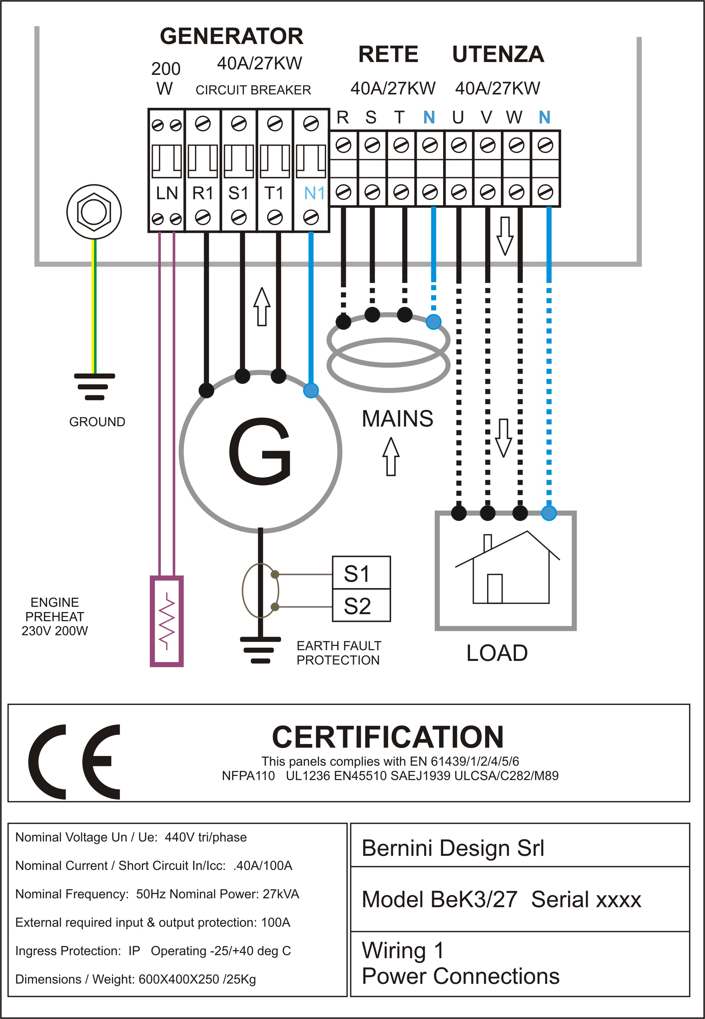
Power connections of a 27kVA AMF generator control panel equipped with the BeK3 AMF controller
The recent updates IEC61439 are in force. Electric panel makers have to re-adapt the design of the panels to comply with these specifications. Complex JOB for AMF and ATS Genset Panel makers. The Bernini Design BeK3 Series Electric Panels fully comply with IEC61439-1-2-3-4-5-6-7 (https://en.wikipedia.org/wiki/IEC_61439_standard) and NFPA110 standards too. With these new rules the entire structure has been completely changed. The new line of AMF ATS panels includes the CANBUS compatible with SAE J1939. The RS485 supports completely the MODBUS-RTU standard. By using our line of 25-500kVA AMF AT
Tidak ada komentar:
Posting Komentar